DESIGN YOUR MONSTER
YOUR ELECTRONICS
Before you start working on your project, it’s good to know a bit more about the electronics you’ll be using.
You’re familiar with the LilyPad Arduino SimpleSnap. You’ve also worked with LEDs before, but the Lily-Pad SimpleSnap Protoboard (which we’ll also call the Protoboard) and the LilyPad Speaker are new.

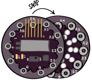
The Protoboard is the board with a ring of male snaps around its outer edge and holes in its center. The Protoboard snaps onto the LilyPad Arduino SimpleSnap. Try snapping the two boards together. Notice that they’ll only snap together in one orientation. Try taking them apart—this can be tricky! If you’re having trouble, wedge something stiff like a pair of scissors in between the two boards and gently pry them apart.
In this project you’ll sew the Protoboard to your monster and snap the LilyPad to it. This will enable you to reuse your LilyPad in other projects. Notice how the Protosnap has labels on each of its snaps that correspond to the labels on the LilyPad.
The LilyPad Speaker, as you probably guessed, can make sounds when you send it the right kind of signal. It’s also called the LilyPad Buzzer. You may see “Buzzer” instead of “Speaker” on your packaging. If so, don’t worry—you still have the right part! This tutorial will call the board the LilyPad Speaker or simply the speaker.
BASIC DESIGN
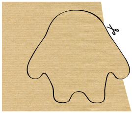
Begin by designing a shape for your monster and drawing it on a piece of paper.
Your design should fit easily on a sheet of standard letter paper (8.5” x 11”). Cut out your shape to use as a template.
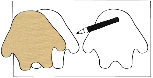
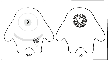
Note: As you design and build your monster you have to keep careful track of the front and back pieces and the inside and outside of your monster. All of the design drawings here show the outside of the monster.
On a blank sheet of paper (ideally size 11”x 14”), use the template to trace out two copies of the monster, one next to the other. Label one as the front of the monster and one as the back.
Decide on a color scheme for your monster and give it some personality. (You’ll glue felt decorations to your monster after you build it.)
What will its eyes and mouth look like? Will it have claws? Toenails? Sketch these details on your design.

CIRCUIT DESIGN
Once you’ve created your monster character, decide where you want to put your Protoboard (the LilyPad will snap onto this board), LED, and speaker and add these components to your design.
Keep all of these pieces on the outside of your monster. Here, the Protoboard is on the back of the monster and the LED and speaker are on the front of the monster.
You can make your circuit diagram on your character sketch, or make a new drawing for the electrical elements. Do whatever you think will be most helpful.
Now that you know where the components will go, you need to figure out how to connect them. Start with the LED.
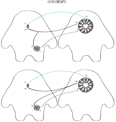
The (-) tab on the LED should be attached to the (-) tab on the LilyPad. The (+) tab on the LED should be attached to one of the numbered tabs on the LilyPad—tab A4 for the monster here. (Remember that each of these connections is called a “trace” in the universe of electronics.) Sketch the (-) trace in black and the other trace in another color.
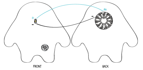
Next, plan the speaker connections. The (-) tab on the speaker also needs to be attached to the (-) tab on the LilyPad and the (+) tab on the speaker should be attached to another tab on the LilyPad—any tab except (-) or (+) will do. Here, the (+) tab of the speaker is attached to pin 5.
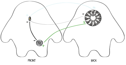
You may have noticed that instead of connecting the (-) side of the speaker to (-) on the LilyPad, it’s connected to the (-) side of the LED. You could connect the (-) tab of the speaker anywhere along the trace from (-) on the LilyPad to (-) on the LED. Electrically, all of these points are connected. It doesn’t matter where you attach the (-) side of the speaker as long as it’s somewhere along the (-) trace.
Use your colored pencils to add the connections to your drawing. Remember that black is used for (-) connections. The connections for your LED and speaker should be drawn in another color.
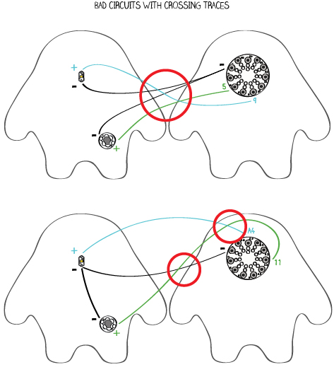
CIRCUIT PLANNING GUIDELINES
• Don’t let traces from different pins or tabs cross each other or get too close to each other. When two different traces touch each other this creates a short circuit (like the ones described in the bookmark tutorial). In the monster, short circuits will cause the LED and speaker to malfunction and, in the worst case, may damage the LilyPad or its battery.
• It’s OK for two of the same electrical traces to touch each other—like the (-) traces for the LED and speaker.
• Make sure you always plan out your circuit before you start building. Without careful planning, you will end up creating short circuits, sewing unnecessarily long traces, and having to take out and re-sew stitches during construction.