DESIGN YOUR BRACELET
THE LILYTINY
Before you start designing, it’s useful to know a bit more about the LilyTiny—a tiny computer in a sewable package. Take it out and look at it. The small black square in the center of the LilyTiny is a computer chip called a microcontroller. It looks a little like a spider with its eight legs. These legs are called pins in electronics terminology. Notice that the LilyTiny board has six silver tabs labeled (+), (-), 0, 1, 2, and 3. Each one of these tabs is connected to one of the pins on the chip. If you look closely at the board you can see the conductive traces that make these connections. Because tabs are generally attached to pins, we’ll refer to pins and tabs interchangeably throughout this volume.
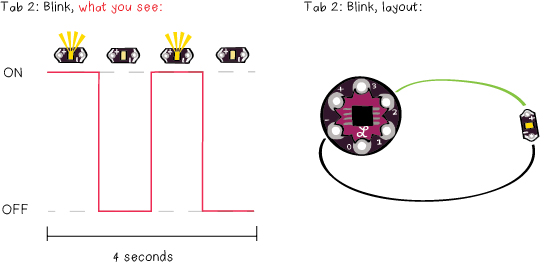
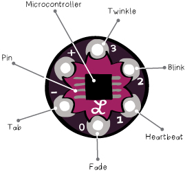 The LilyTiny has been programmed so that an LED attached to each of these tabs will behave differently. If you attach the (+) tab of an LED to the tab labeled 0, the LED will gently fade in and out. If you attach it to tab 1 it will thump on and off in a heartbeat pattern. If you attach it to tab 2 it will blink steadily. Finally, if you attach it to tab 3 it will twinkle like a candle.
(Note: If you attach it to the (-) tab it won’t turn on at all and if you attach it to the (+) tab it will stay on all the time.)
You’re probably familiar with some of these LED behaviors from your day-to-day life: the fading LED on a sleeping apple computer, blinking Christmas lights, and LED “candles”. In each of these cases there’s a tiny computer like the LilyTiny generating that behavior. The moral of the story here is that the computer chip on the LilyTiny lets you make more interesting and dynamic projects than you could make with just an LED and a battery. This gives you a little glimpse into the power of computers—a topic we’ll continue to explore throughout this book. Keep these LED behaviors in mind as you work on the design for your bracelet.
BRACELET DESIGN
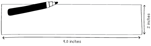
The first thing you need to do is figure out how long your bracelet should be. Get out the tape measure, a pencil, and a sheet of paper. Wrap the tape measure around your wrist and write down the measurement. (Note: If you don’t have a flexible tape measure, wrap a piece of string around your wrist and mark where one end touches the other. Then use a ruler to measure this length of string.) Your bracelet will need to be at least 2.5” (6cm) longer than this measurement—this will give you room to attach snaps. The model for the bracelet shown in this tutorial had a wrist that’s 7” (18cm) around, so the bracelet shown here will be 9.5” (24cm) long.

On a piece of paper, draw the outline for your bracelet. It should be at least 2” (5cm) wide so that all of the electronics can fit on it comfortably.
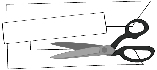
Cut out your bracelet outline to use as a template. On a fresh piece of paper, use the template to create a new bracelet outline for your design drawing. Put the bracelet template aside. You’ll use it again in a moment.
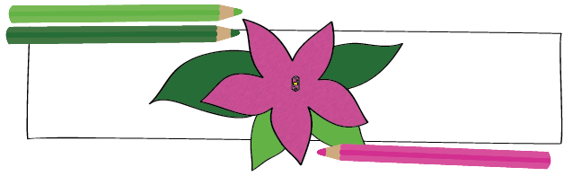
Decide on a color scheme and look for your bracelet. Add these elements to your sketch. Think about which LED behavior you want, where you want your LED to be, and whether you’d like to hide it with decoration or leave it exposed. In the example here, the LED is covered with a pink flower.
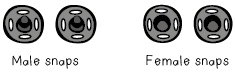
Place the battery holder on one side of the bracelet about 1/2” (10mm) from the edge. Design your closure and mark out where your snaps will go on your design. You should have two sets of snaps: two male snaps and two female snaps.
To make a closure that covers the battery holder, the male snaps should be attached just in front of the battery holder, in between the battery holder and the rest of your design. The female snaps should be attached to the other end of the bracelet on the other side of the felt.
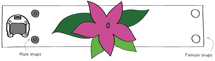
When the bracelet is closed, a flap of fabric will cover the battery holder.

CIRCUIT DESIGN
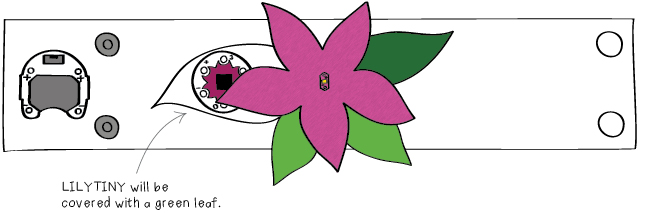
You’ve decided where you want to put your LED. Now decide on the placement for your LilyTiny. You want to keep the LilyTiny close to the battery so that it’ll be easy to sew. Mark the LilyTiny location on your design sketch. Next, you want to plan out how you’re going to connect the components to each other. You can make your electrical diagram on your bracelet design sketch, or make a new drawing for the electrical elements. Do whatever you think will be most helpful. This page will show the electrical design on its own.
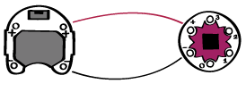
Draw the connections between the battery holder and the LilyTiny. Connect one of the (+) tabs on the battery holder to the (+) tab on the LilyTiny and one of the (-) tabs on the battery holder to the LilyTiny’s (-) tab. As in the bookmark project, (+) connections should be drawn in red and (-) connections should be drawn in black.
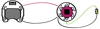
Sketch the connections for your LED. Draw the connection between the (–) side of your LED and the (–) tab on the LilyTiny in black. Then, draw the connection between the (+) side of your LED to the behavior tab you’ve chosen in a different color. In this tutorial, the LED’s (+) tab is attached to tab 0, but you can choose tab 0, 1, 2, or 3. The LilyTiny section at the beginning of this chapter describes the behavior of each tab.
At this point, you may be faced with crossing traces or a complex electrical layout. If this is the case, adjust your design by moving your components and re-drawing your connections. You may also want to change your decorations to hide or show off connecting traces and electronic components. Edit your design until you have something that you’re happy with.