DESIGN YOUR PIANO
PIANO KEYS AND CAPACITIVE SENSING
Before you begin designing, you should know a bit more about the “piano keys” that will be part of this project. Each key will be a touch sensor constructed out of conductive thread. The touch sensor you built for the interactive monster required you to touch two conductive patches—the monster’s two paws. In this project, you’ll use a different kind of touch sensor called a capacitive sensor. With a capacitive sensor, you only need to touch one conductive patch.
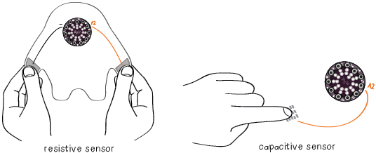
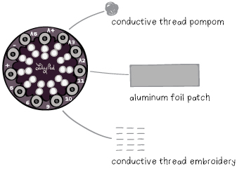
The circuitry for a capacitive sensor is simple. You attach a conductive patch or sew a conductive trace to a pin. That pin is then programmed to detect when a person touches the patch or trace. You’ll explore how this touch sensing works in a moment. For now, it’s important to know that the LilyPad will be able to detect when your skin contacts the conductive patch or trace. The larger the conductive area is, the more sensitive the touch sensor will be. Three examples of sensors are shown below.
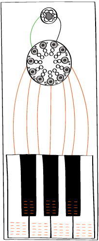
The piano you’ll build has seven keys and a sewn-in LilyPad speaker. Each key will be a single trace of stitching in conductive thread connected to a pin on the LilyPad. The piano will be able to detect when you touch any one of these sensor keys.
BASIC DESIGN
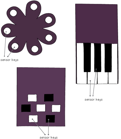
Decide on a shape and color scheme for your piano and its seven keys. Draw out your pattern on a sheet of paper. Keep in mind that your sensor keys will need to be sewn to your LilyPad Arduino.
Be creative with your piano! The sensor keys don’t have to be any particular shape or size.
CIRCUIT DESIGN
Decide where you want to place your LilyPad and speaker. Draw out the trace for each sensor key. You can be creative with the conductive thread stitching for your sensors—you might use an embroidery stitch, spell something out in stitches, or sew out a decorative flower. Remember though to keep the traces for different keys as far apart as possible to prevent shorts.
The (+) tab on the speaker needs to be attached to one of the numbered tabs on the LilyPad and the (-) tab on the speaker needs to be attached to the (-) tab on the LilyPad. Draw these connections out on your sketch.